Thermal management techniques for printed circuit boards
Most electronic components generate heat whenever current flows through them. The amount of heat depends on the power, the characteristics of the electrical device, and the circuit design. Certain components, electrical resistance of connections, number of holes and copper traces in the circuit also contribute to heat dissipation and power dissipation.
To avoid failures or poor circuit performance, designers should strive to produce circuit boards that remain within safe temperature limits. While some circuits will operate without additional cooling, there are situations where the addition of heat sinks, cooling fans, or a combination of several mechanisms at once is unavoidable. Therefore, we will now focus on manufacturing practices that allow for better control and temperature reduction of the resulting printed circuit board.
Best Practices for PCB design
The following issues should be considered when designing printed circuit boards:
- Performance data and component dimensions
- Major heat dissipating components
- PCB size
- PCB component material, layout and placement
- The placement of peripheral devices
- Application ambient temperature
- Amount of heat dissipation
- Suitable cooling methods, i.e. cooling fans, heat sink etc.
The best practice is to optimize the temperature at component level with respect to the operating environment.
Factors to consider when deciding on the cooling mechanism include semiconductor properties, heat dissipation characteristics etc. This information is usually available in the datasheet or datasheet from the manufacturer.
At the same time, natural convection cooling is suitable for PCBs with a small amount of heat dissipation. PCBs with large heat dissipation, however, require heat sinks, heat pipes, fans, dense copper, or a combination of several cooling techniques together.
Thermal resistance expresses the area of a structure and the temperature difference across its surfaces that will transfer 1 Watt or 1 J of energy in 1 second. It has the designation R and the unit [m2-K/W].
Thermal resistance R = d / λ
λ (lambda) is the coefficient of thermal conductivity
d material thickness
The thermal resistance R is a physical quantity that expresses the thermal insulation properties of a material or an entire structure. More specifically, the thermal resistance indicates how the structure 'impedes' the passage of heat through the structure, with the greater the resistance, the slower the heat passes through the material or structure.
Designers often reduce thermal resistance by:
- using thinner circuit boards to shorten the thermal path,
- adding through holes for vertical heat dissipation,
- inserting copper foil and thick strips for horizontal heat conduction.
Identification of Components with the Potential to Dissipate more Heat
It is important to understand which components generate the most heat and decide on the best heat dissipation mechanism. Using the manufacturer's datasheet, the designer should determine the thermal performance and characteristics of the device. Often manufacturers will provide instructions on how to remove excess heat from the equipment.
In PCB technology, the heat source and heat sink are often located on opposite sides of the PCB. Common FR4 PCB materials have relatively low thermal conductivity in the range of about 0.3-0.5 W/mK. Using a core material with good thermal conductivity - usually metals - will improve heat dissipation (1.3-4.2 W/mK). These metal-core (IMS) boards are most effective when designed as single-sided. There are also special laminates with similar thermal conductivity values to IMS, but they cost many times more than conventional materials.
Consider the Location, Orientation and Arrangement of Components
- Structural elements that radiate more heat energy should be placed in locations that provide the best heat dissipation. If a heat sink is not available, components may be placed in corners or on edges. To ensure heat dissipation around the equipment, components should be placed close to the centre but with sufficient space for adequate air circulation.
- While it may be difficult to ensure even temperature distribution, it is important to avoid concentrating powerful components in one location. Spreading them evenly will prevent hot spots.
- Another good practice is to place sensitive components such as small integrated circuits, transistors and electrolytic capacitors in low temperature locations. For circuits that depend on convection cooling, arranging components such as integrated circuits in a horizontal or vertical longitudinal manner helps control the temperature.
How to Identify Thermal Problems with Printed Circuit Boards
Designers can use a variety of techniques to identify potential problems. Popular approaches include using thermal analysis tools, visual inspection and infrared cameras.
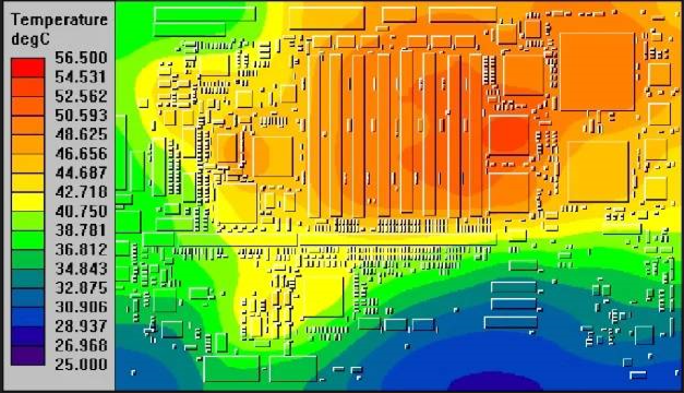
Thermal Analysis
Performing a thermal analysis can help you determine how components and the circuit board will behave under different temperatures and conditions. The analysis gives designers an idea of heat generation and transfer in the circuit.
Designers can then use the results of the analysis and simulations to design techniques to help them better manage heat.
Visual Inspection of the Board without Power
Visual inspection is an easy way to find signs of overheating, burned or partially damaged components, dry joints, arcs etc. Visible signs include bulging components, burnt components and discoloured areas on the circuit board. In addition to visual analysis, the smell of a burnt circuit board may indicate heating problems.
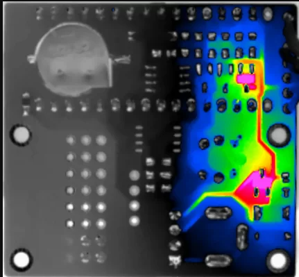
Using infrared Cameras
Infrared cameras can be used to evaluate the thermal heating of powered prototype boards and to identify overheating not visible to the naked eye. In addition to showing areas of excessive heating, the cameras can sometimes identify counterfeit or defective components whose thermal characteristics differ from the thermal signatures of the original components.
Thermal cameras can also detect those places where there is insufficient solder, i.e. a place with higher resistance and greater heat dissipation.
How to remove heat from printed circuit boards
There are several techniques that designers can use to remove heat from components and printed circuit boards. Common mechanisms include heat sinks, cooling fans, heat pipes, and a thick layer of copper. Circuits that generate more heat most often require more than one technology. For example, cooling a laptop's processor and display chips usually requires a heat sink, a heat pipe, and a fan.
Heat Sinks and Cooling Fans
A heat sink is a thermally conductive metal component with a large surface area that is typically attached to components such as power transistors and switching devices. A heat sink removes heat from the component and transfers it to the surrounding area. Especially for high current power supplies, adding a cooling fan helps dissipate heat faster.
Heat pipes
Heat pipes are suitable for compact installations with limited space. The tubes provide reliable and cost-effective passive heat transfer. Advantages include vibration-free operation, good thermal conductivity, low maintenance and quiet operation as they have no moving parts.
A typical tube contains small amounts of nitrogen, water, acetone or ammonia. These liquids help to absorb heat, after which they release steam that spreads along the pipe. The pipe has a condenser where, as the steam passes, it condenses back into liquid form and the cycle begins again.
Thermal Via Arrays
Another way is to connect the heat sources to the cooler by means of so-called thermal bushings. These consist of a series of 'thermal vias' between two contact surfaces where the heat source and the heat sink must be connected at the points of least resistance to heat transfer. A higher number of plated holes reduces the thermal resistance.
The plated holes have a copper surface that reduces thermal resistance and improves heat dissipation from critical parts of the line. Therefore, better performance is achieved when the holes are located closer to the heat source. On the other hand, they increase the weight of the circuit board, but mainly take up space on the board and increase the difficulty and cost of manufacturing due to the density of the drilling. The vias provide only a few degrees of temperature difference compared to a bushing without vias, and this difference is localized very close to the vias themselves.
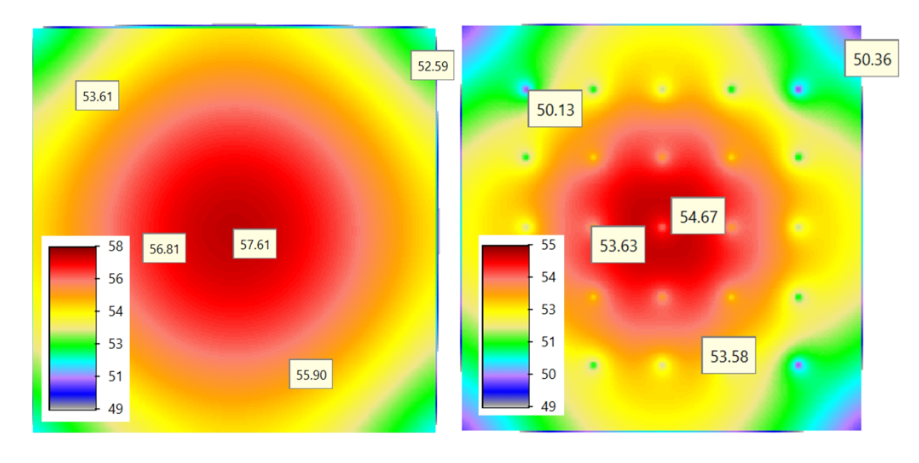
Fig. 1: A casing without vias is shown on the left and a casing with 25 vias on the right.
If there is not enough space, filling the holes with a thermally conductive material may be the solution. Either copper (for micro-holes) or conductive pastes filled with silver are used. However, these technologies are much more expensive, so the technology that is most suitable for the purpose should always be considered. Filling with non-conductive paste may be a compromise if the holes are subsequently re-soldered (via Type VII filler).
In some applications, heat is dissipated from a device, such as a thermally optimised integrated circuit, by a combination of through-hole and blind-hole arrays and copper plates. This eliminates the need for a heat sink while improving heat dissipation across the PCB.
Thick Copper traces
Using more copper provides a larger surface area to help distribute and dissipate heat. Such circuit boards are suitable for high power applications.
COIN Technology
One way to remove heat from a specific location is to press a copper ingot into the plate. However, this technology requires precision CNC machining and special stamping tools and process. Also, the varying expansion of materials can be a problem under long-term loading.
If you need to have thermally optimized circuit boards, designers need to have already considered everything that affects temperature right up to the concept stage and possibly optimized the layout during the design and manufacturing phase.
Connect with our specialists