Rigid-flex is a hit. We'll tell you why
Why flexible PCB?
Flexible PCB bring completely new possibilities in the design of electronics because HW designers are not limited to two dimensions as with a rigid board. They can therefore adapt the resulting shape exactly to the shape of the product. Flexible PCB also facilitate component installation, reduce the risk of wiring errors and reduce testing requirements. In addition, these borads are designed to withstand higher temperatures, harsh environments, and many bends (thousands to millions of cycles), and also withstand vibrations well.
Advantages and comparison of rigid vs. flexible
The main advantage of flexible PCB is saving space and weight. High-quality design can save up to 75% of volume and weight compared to rigid boards. One flexible PCB can replace several rigid boards, cable harnesses and connectors. For flexible PCB, it is not necessary to monitor the colour coding of the wires and the wiring harnesses. This saves the time required for testing, rework or repairs. In addition, flat joints dissipate heat much better than conventional wires of the same cross-section. For flexible boards, it is also easier to calculate and predict noise, crosstalk and impedance characteristics. In addition, flexible PCB have uniform electrical characteristics.
Price of flexible PCB
The price of a flexible PCB is determined mainly by the materials used. If we only compare the price of the raw material, the price of a flexible PCB is about twice as much, given the same parameters. On the other hand, it is necessary to take into account not only the cost of materials, but also the cost of installing or connecting wires, connection testing and repairs. Especially for larger series, these items are a significant part of the price. With a clever design of the board and production panel, it should be possible to achieve a price about 50% higher, but balanced by better properties and durability of the base material.
What is production governed by
For the design of flexible PCB, we recommend using newer design software (Altium designer, etc.), which is able to work with flexible materials, but also calculate the required characteristics and display boards in three dimensions. The production itself is governed by the current standard IPC 600 for the production of printed circuit boards, and especially the part IPC-6013 for flexible boards.
Semi-flex
This technology can in some cases replace a flexible boards. But only when there is no multiple bending of the joint. By nature, each board is flexible because it is made of glass fibres and resin. Therefore, if we cut away the material from one side and leave at least the necessary minimum of 200 µm, it is possible to bend such a board once and place it in the device. It is necessary to observe the minimum radius (according to the type of material and its thickness, but at least 5 mm) and use a special flexible solderless mask.
Materials, rolled vs. electrolytic copper
For flexible joints it is necessary to use a much more flexible material. The most commonly used material is polyimide (PI). This material is very flexible and cannot be easily torn or broken. It also withstands high temperatures well and has low thermal expansion. It is therefore possible to perform several soldering cycles in succession. One alternative may be to use polyethylene (PET), which is a cheaper alternative but does not withstand high temperatures, so it is not recommended for component placement. Therefore, Gatema does not use it, not even for the production of the simplest flexible joints.
Copper on the flexible core can be deposited electrolytically (ED) or rolled (RA). Electrolytic copper can be used as a substitute for a cable harness that does not provide for a high number of bends. For all other products, we recommend using rolled copper, which has been proven to withstand hundreds of thousands of bends. This is especially true for prototype production, where the price savings are not significant enough to justify the risk of a board with a non-functional flexible joint.
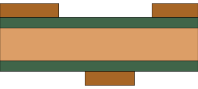
Cores
Gatema uses Thinflex for cores; it is also possible to use Pyralux. The thickness of the core is 50 µm, the thickness of copper can be 18 or 35 µm.
Coverlay or solder mask
In the design of the flexible part of the board, it is possible to use either a flexible mask or a coverlay - a polyimide cover layer (Pyralux®), or their combination. A flexible mask is suitable where there is no extreme stress (up to 20 cycles during the life of the product). For rigid-flex boards with an inner joint, it is always necessary to use a coverlay. The same applies to high-stress joints and to joints with components. Gatema offers coverlay in one thickness of 25 µm polyimide and in two different thicknesses of acrylic adhesive 25-50 µm, selected on the basis of the resulting height of the Cu pattern.
Stiffener
If the flexible joint is used instead of a connector, it is possible to support the flexible joint with a FR-4 board with a thickness of 0.1-1.5 mm. This support is glued to the board with double-sided tape. It is also possible for us to make a flexible joint only with adhesive tape which attaches the joint only when the assembly is connected. Gatema use 3M double-sided adhesive tapes with an adhesive thickness of 0.05 mm and 0.130 mm with a temperature resistance of up to 220°C for production.
Tips for production (tear drop, staggered joints, hexagons, bends in the corners, connecting wires, data preparation).
-
For data preparation, we recommend using design software that is intended for flexible joints. The design should comply with the standard IPC 2223 (Sectional Design Standard for Flexible / Rigid-Flexible Printed Boards). We also recommend getting acquainted with the current technical possibilities of the manufacturer here.
-
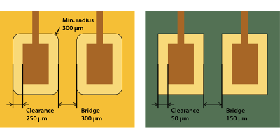
Flexible joints provide an excellent resistance to vibrations, but on the other hand it is necessary to bear in mind that the connections and soldering points are subjected to greater stress and must be designed with regard to their use. We recommend designing the solder pads as large as possible.
-
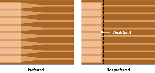
If it is necessary to change the width of the wire in the flexible part, it is better to make such a transition as smoothly conical.
-
When connecting solder pads, it is necessary to use tear drop.
-
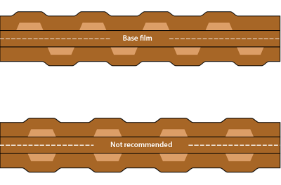
For multilayers, avoid applying joints on top of each other if possible.
-
-
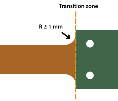
For rigid-flex PCBs, it is necessary to pay attention to the minimum distance via holes (1-2 mm) from the transition area.
-
Use a cutter with a radius of at least 1 mm in the transition zones, or see the sample.
-
If you need to increase the final thickness of the board or strengthen it somewhere, use a stiffener.
-
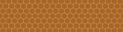
Ground must be hatched (preferably hexagonal) in the flexible joint.
-
Unmasking with a coverlay has different parameters than unmasking with a flexible green mask.
-
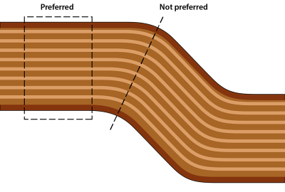
The wires at the bending point should run straight.
-
If possible, place a wider joint on the outer side of the flexible joint to prevent the joint from tearing apart.
Connect with our specialists